(Ultra) Cheap microphone array
- Jun 25, 2015
- 5 min read
I was cleaning up my files when I found my final university project: A microphone array using microchip. I have been looking for cheap COTS microphone array or cheap and performant DIY projets on the web without much success. So I though I should share my experiment with the community. I may eventually work on getting it at a larger scale.
Lets discuss about what is a microphone array first. Basically in a video, you have an array of photosite that are exited over time. Each photosite (or pixels) represent the luminosity at a certain time and at a certain position. The possibility of localizing the content for each location is due to the lens that make the focus on the area of interest. An audio lens is also possible, although not at any useful scale. So in order to "focus" audio" in space we have to turn out to alternative. One of them is using a microphone array.
A microphone array use delays and multiple microphones tobe able to approximate the sound intensity in space. It is also know as Delay and Sum Beamforming.
If we make the assumption that the source is relative far away compared to the spacing between the microphone (which is typically the case) we can consider the audio path to be parallel. That mean if each microphone are recording simultaniously that the difference of delay between each microphone in a evently spaced on a linear array is given by:

y=d*sin(theta)/v
Where:
y: is the difference of delay (s)
d: is the space between the microphone (m)
v: is the speed of sound (~343 m/s)
theta: is the angle in radian
N: is the number of microphone
In the frequency domain, a delay applied to a signal is an exponential. Replacing the delay with the previous equation and by summing for each microphone we get the following formula:
Gain(f,theta) = Sum[e^(2*pi*i*n*d*sin(theta)/v)]
Where:
Gain(f,theta): is the normalized gain in function of the frequency and the angle
e: is the Euler number ~2.71
pi: is ~3.14
i: is the imaginary number sqrt(-1)
n: is the term used for the sum. Sum for n=0 to N-1.
Now enough theory, let's go to the practice! The implementation I did was using the following parts:
4x Electret microphones
1x LM324
1x DSPIC30F2012
1x DAC MCP4822
4x AA NI-MH
All those part are pretty cheap, excluding the battery it should cost bellow 15$! The system is 12 bits, so it may not be comparable to 24bits audio, but as the microphone and pre-amp used have relatively limited dynamic range, 12 bits is adequate. So there is the montage and schematic:

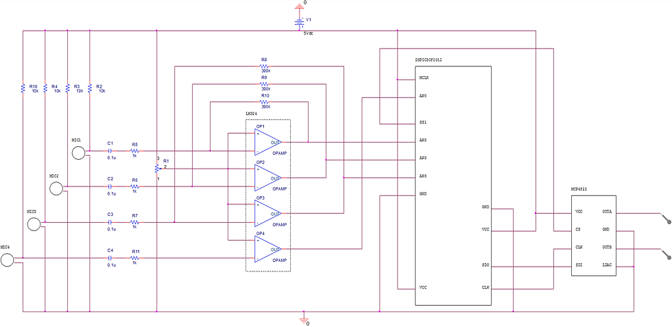
March 10th, 2018 update: A better quality of the schematic is available here...
May 22th, 2018 update: There is an error on my schematic. We can read from top to bottom on the left side: MCLR, AN0, SS1, AN3, AN3, AN3, GND and VCC. It should read as: MCLR, AN0, SS1, AN3, AN4, AN5, GND and VCC.
The microphone powering, voltage offset and gain is done using a single op-amp per microphone!
Main code:
#include <p30f2012.h>
main() {
VisualInitialization(); //Initialization of uart and analog inputs
while (1) {
while(SPI1STATbits.SPITBF); //Wait the end of transmission
SPI1BUF=4096+ADCBUF0+ADCBUF1+ADCBUF2+ADCBUF3)/4; //Output A : Average
while (SPI1STATbits.SPITBF); //Wait the end of transmission
SPI1BUF = 32768+4096+ADCBUF0; //Output B : First element only
}
}
The results are pretty good at rejecting side noises. With 3 microphones and a spacing of 0.068m the following results were obtained.
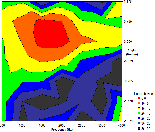
Anything below 600Hz and around 4000Hz doesn't get much filtered out as expected with the theorical formula above. More elements and more spacing could fix this, although for voice application this combinaison is relatively compact and effecient!
Let me know if you attempt to build one or if you have any improvements!
May 22th, 2018 Update:
Following a question on the content of the VisualInitialization() function here are more details. In the legacy version of MPLAB IDE I used, there was a nice graphical interface to configure the microchip and it was producing the required assembly code to do it. Here is what that tool used to look like: (With actual settings to configure the microchip for the array.)


Next is the produced assembly code from the visual initializer. It can feel scary at first, but there are a lot of comments, it would be about 10 lines of C code.
; Initialization Code for dsPIC30F2012, Family: sensor control, Package: 28-Pin PDIP 28pins
.include "p30F2012.inc"
; Filter Controls used to Generate Code:
; POR Match Filter ON
; Provisioned Feature Filter ON
; Masks are Ignored and uses UnMasked Register Writes
.GLOBAL _VisualInitialization
; Feature=fuses - fuses (DCR) configuration
; B15:14=FSCKM1:0 B10:8=FOS2:0 B4:0=FPR4:0
; B15=FWDTEN B5:4=FWPSA1:0 B3:0=FWPSB3:0
; B15=MCLREN B7=BOREN B5:4=BORV1:0 B3:0=FPWRT3:0
.text
_VisualInitialization:
; Feature=Interrupts - Disable Interrupts during configuration
; clear int flags:
; B15=CN B14=BCL B13=I2C B12=NVM B11=AD B10=U1TX B9=U1RX B8=SPI1
; B7=T3 B6=T2 B5=OC2 B4=IC2 B3=T1 B2=OC1 B1=IC1 B0=INT0
; B15:12=IC6:3 B11=C1 B10=SPI2 B9=U2TX B8=U2RX
; B7=INT2 B6=T5 B5=T4 B4=OC4 B3=OC3 B2=IC8 B1=IC7 B0=INT1
; B12=FLTB B11=FLTA B10=LVD B9=DCI B8=QEI
; B7=PWM B6=C2 B5=INT4 B4=INT3 B3:0=OC8:5
; Feature=Reset - Reset configuration
; B15=TRAPR B14=IOPWR B13=BGST B12=LVDEN B11:8=LVDL3:0
; B7=EXTR B6=SWR B5=SWDTEN B4=WDTO B3=SLEEP B2=IDLE B1=BOR B0=POR
; Feature=NVM - NVM configuration - not implemented
; Feature=Oscillator - Oscillator configuration
; Method to override OSCCON write protect
; B13:12=COSC1:0 B9:8=NOSC1:0
CLR.B W0
MOV.B #0x78, W1
MOV.B #0x9A, W2
MOV.W #OSCCON, W3
MOV.B W1, [W3+1]
MOV.B W2, [W3+1]
MOV.B W0, [W3+1]
; B7:6=POST1:0 B5=LOCK B3=CF B1=LPOSCEN B0=OSWEN
CLR.B W0
MOV.B #0x46, W1
MOV.B #0x57, W2
MOV.B W1, [W3+0]
MOV.B W2, [W3+0]
MOV.B W0, [W3+0]
; Feature=A2D - A2D configuration
; force all A2D ports to digital IO at first
MOV #0xFFFF, W0
MOV W0, ADPCFG
; Feature=SPI1 - SPI configuration
; SPInBUF: SPI n buffer
; SPInSTAT: B15=SPIEN B13=SPISIDL B6=SPITBF B5=SPIROV B0=SPIRBF
; SPInCON(H): B14=FRMEN B13=SPIFSD B11=DISSDO B10=MODE16 B9=SMP B8=CKE
; SPInCON(L): B7=SSEN B6=CKP B5=MSTEN B4:2=SPRE2:0 B1:0=PPRE1:0
MOV SPI1BUF, W0
MOV #0x8000, W0
MOV W0, SPI1STAT
MOV #0x4460, W0
MOV W0, SPI1CON
; Feature=A2D - A2D configuration
; B15:0=CSSL15:0
MOV #0x0038, W0
MOV W0, ADCSSL
; B15:14=CH123NB1:0 B13=CH123SB B12=CH0NB B11:8=CH0SB3:0
; B7:6=CH123NA1:0 B5=CH123SA B4=CH0NA B3:0=CH0SA3:0
; B15:0=PCFG15:0
MOV #0x03C7, W0
MOV W0, ADPCFG
; B12:8=SAMC4:0 B7=ADRC B5:0=ADCS5:0
; B15:13=VCFG2:0 B12=OFFCAL B10=CSCNA B9:8=CHPS1:0
; B7=BUFS B5:2=SMPI B1=BUFM B0=ALTS
MOV #0x0408, W0
MOV W0, ADCON2
; B15=ADON B13=ADSIDL B12=ADSTBY B9:8=FORM
; B7:5=SSRC B3=SIMSAM B2=ASAM B1=SAMP B0=CONV
MOV #0x80E4, W0
MOV W0, ADCON1
; Feature=required - Interrupt flags cleared and interrupt configuration
; interrupt priorities IP
; B14:12=T1 B10:8=OC1 B6:4=IC1 B2:0=INTO
; B14:12=T3 B10:8=T2 B6:4=OC2 B2:0=IC2
; B14:12=AD B10:8=U1TX B6:4=U1RX B2:0=SPI1
; B14:12=CN B10:8= BCLB6:4=I2C B2:0=NVM
; B14:12=OC3 B10:8=IC8 B6:4=IC7 B2:0=INT1
; B14:12=INT2 B10:8=T5 B6:4=T4 B2:0=OC4
; B14:12=C1 B10:8=SPI2 B6:4=U2TX B2:0=U2RX
; B14:12=IC6 B10:8=IC5 B6:4=IC4 B2:0=IC3
; B14:12=OC8 B10:8=OC7 B6:4=OC6 B2:0=OC5
; B14:12=PWM B10:8=C2 B6:4=INT4 B2:0=INT3
; B14:12=FLTA B10:8=LVD B6:4=DCI B2:0=QEI
; external interrupt enables
; B15=NSTDIS B10=OVATE B9=OVBTE B8=COVTE
; B4=MATHERR B3=ADDRERR B2=STKERR B1=OSCFAIL
; B15=ALTIVT B4:0=INTnEP4:0
; Feature=CPU - CPU register configuration
CLR SR
CLR SR
CLR W0
CLR W1
CLR W2
; Feature=Interrupts - enable interrupts
; Feature interrupt enables IE
; B15=CN B14=BCL B13=I2C B12=NVM B11=AD B10=U1TX B9=U1RX B8=SPI1
; B7=T3 B6=T2 B5=OC2 B4=IC2 B3=T1 B2=OC1 B1=IC1 B0=INT0
; B15:12=IC6:3 B11=C1 B10=SPI2 B9=U2TX B8=U2RX
; B7=INT2 B6=T5 B5=T4 B4=OC4 B3=OC3 B2=IC8 B1=IC7 B0=INT1
; B12=FLTB B11=FLTA B10=LVD B9=DCI B8=QEI
; B7=PWM B6=C2 B5=INT4 B4=INT3 B3:0=OC8:5
return


Comments